ISOMX1ParkerTD
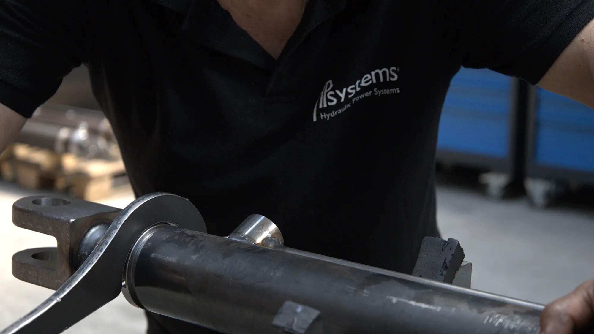
Tie rods extended both ends
Tie rods extend from both ends of the cylinder. Head and cap provide a fixing point on each side.
Application
Press, fixed hydraulic assembly, industrial requiring double-sided fixing.
Whichever mounting type you need — send a drawing, project or sample and we produce it. Including types in no catalog, found nowhere in the world.
52 mounting types: 39 standardised combinations (ISO 6099 + ISO 6020-2 + NFPA T3.6.7R + Parker code mapping) + 8 rod end variants + 5 special custom designs. Types not found in standard catalogues are also produced from a customer drawing.
Five real types from the HPS production catalogue: plain end, cross tube, cross tube + rod eye, flat tang eye and spherical-bearing eye. Every mounting type is applied to the customer's drawing.
Mounting combinations are coded in three main standards. Most manufacturers use all three codes in parallel. Mapping from one to another is possible.
Single-rod compact series mounting dimensions. MF / MS / MT / MP / MX / ME code families.
Heavy-duty mounting reference at 25 MPa pressure. Press and heavy machinery applications.
Imperial-unit-based US market mounting coding. T3.6.7R for the square head tie-rod class.
Fixed centerline mount with tie-rod extension. Extends from one or both ends.
Tie rods extend from both ends of the cylinder. Head and cap provide a fixing point on each side.
Tie rods extend only from the cap (non-rod) end. Single-sided fixing.
Tie rods extend only from the head (rod side) end. Connection to the chassis on the rod side.
The rod extends from both ends and the tie rods provide mounting at both ends. Equal speed and force in both directions.
Fixed mounting with a flange plate. The most common choice for presses and fixed industrial applications.
Rectangular flange plate at the rod-side end. Fixed to the chassis with 4 bolt holes.
Rectangular flange plate on the cap end. High-tonnage fixed applications.
Round flange plate at the rod-side end. Coaxial application, circular bolt pattern.
Round flange plate on the cap end. Coaxial fixing applications.
Square flange plate at the rod-side end. Symmetric 4-bolt pattern, orientation-independent mounting.
Square flange plate on the cap end. Orientation-independent fixing, symmetric 4 bolts.
Rectangular flange in an intermediate position on the barrel close to the rod side. Fixing at mid-stroke.
Rectangular flange in an intermediate position on the barrel close to the cap side. Additional support at mid-stroke.
Round flange with studs at the head end. The studs fixed to the flange are bolted to the frame with nuts.
Round flange with studs on the rear cap. The stud connection eases alignment during installation.
Square flange at an intermediate position near the head. Direction-independent intermediate fixing with a symmetrical bolt pattern.
Square flange at an intermediate position near the rear cap. Symmetrical additional support at mid-stroke.
Non-centerline mount with foot or side lug. Low profile, fixed cylinders.
Foot/lug profile on one side of the barrel. Single-point fixing, compact mount.
Foot profile on both sides of the barrel. Bottom fixing with a two-bolt pattern.
Lug profile on the barrel centerline. Coaxial foot: moment load is balanced.
Threaded bolt holes (tapped holes) on the side of the barrel. Low-profile flat mount.
Lug profile on the end of the barrel (head or cap). Single-end fixing.
A pair of half-wrap feet clamping the body like a pipe clamp. Bottom mounting without welding to the body.
Reinforced side lug pair for heavy duty. The wide base spreads high thrust forces into the frame.
Side-axis articulated mount. Heavy articulated applications such as machinery booms, cranes and concrete pumps.
Two trunnion pins on the side of the barrel near the rod side. Articulated pivot: rotation + axial load.
Two trunnion pins on the side of the barrel near the cap side. Articulated from the cap side.
Fixed trunnion pin at the middle of the barrel or at a desired intermediate position. Articulated at mid-stroke.
Slidable trunnion in an intermediate position. The pivot point is adjustable to the application.
Trunnion pins on both the head and the rear cap side. Pivoting support with two separate bearing points.
The trunnion pin is offset from the body centreline. Shifts the pivot centre in tight layouts.
Intermediate trunnion with locking collars. Its position can be readjusted in the field and locked by the collars.
Fixed or spherical articulated pivot. Most common for dumpers, trailers and mobile platforms.
Clevis connection at the cap end. Pinned to the chassis, articulated rotation.
Barrel clevis connection at the rod-side end. Articulated rotation from the rod side.
Round eye connection at the cap end. Pinned, simple articulation.
Barrel eye (ring) connection at the rod-side end. Articulated from the rod side.
Spherical bearing joint at the cap end. Three-axis freedom: tolerates side load.
Eye with a spherical bearing at the rod tip. Three-axis freedom: articulated + tolerant.
Single-tang pivot connection welded to the body. Pinned to the frame, a simple and robust pivot point.
Pivot bore inside a tapered nose at the cap end. A compact pivot that fits into narrow pockets.
Pivot with a two-axis gimbal ring. Accommodates angular deflection in two planes at once.
Connection added to the rod tip: eye, clevis, threaded, cross-tube or wrench flats variant.
Round ring connection at the rod tip. The simplest articulated rod end.
Clevis connection at the rod tip: pinned articulated rotation.
Eye with a spherical bearing at the rod tip. Three-axis freedom, tolerates side load.
External thread at the rod tip. For standard threaded connection accessories.
Internal thread at the rod tip. Compact threaded connection, hidden accessory.
Transverse pin tube fitted at the rod tip. Articulated connection with a horizontal pin.
Flat wrench-holding surfaces at the rod tip. A wrench can be applied for bolt tightening.
Keyway connection at the rod end. The key transmits torque and provides positive positioning.
Mounting types not found in standard catalogues are designed and produced in-house at HPS. Including a type that does not exist anywhere in the world, from a single prototype to series production. Send your customer drawing or load profile, and our engineering team designs the mounting.
Cylinder on a fixed pillow block. Special fixed mounting: bearing on the chassis.
Wing-profile mount: wing plates projecting from the side of the barrel. Aerospace and niche equipment.
Bell-crank type articulated connection: rotation transfer via a lever extension.
Custom-designed mount from a customer drawing. Including a type that does not exist anywhere in the world, from a single prototype to series production.
Mounting via a saddle seated on the body and a cross tube. Special geometry suited to tipper body undersides.
39 standard mounting types and their equivalents in the three main coding systems. Most mounts have only an ISO code; ISO codes with no NFPA or Parker equivalent are shown with "-".
| Category | ISO | NFPA | Parker | Name |
|---|---|---|---|---|
| Tie-Rod Extended | MX1 | - | TD | Tie rods extended both ends |
| Tie-Rod Extended | MX2 | - | TC | Tie rods extended cap end |
| Tie-Rod Extended | MX3 | - | TB | Tie rods extended head end |
| Tie-Rod Extended | MX4 | - | TDDX | Double rod with tie rods |
| Flange | MF1 | J | REF2 | Head rectangular flange |
| Flange | MF2 | H | BEF2 | Cap rectangular flange |
| Flange | MF3 | - | - | Head round flange |
| Flange | MF4 | - | - | Cap round flange |
| Flange | MF5 | JB | REF1 | Head square flange |
| Flange | MF6 | - | BEF1 | Cap square flange |
| Flange | ME5 | - | - | Head rectangular intermediate flange |
| Flange | ME6 | - | - | Cap rectangular intermediate flange |
| Flange | MF7 | - | REF3 | Head round flange with studs |
| Flange | MF8 | - | BEF3 | Cap round flange with studs |
| Flange | ME3 | - | - | Head-side square intermediate flange |
| Flange | ME4 | - | - | Cap-side square intermediate flange |
| Foot / Lug | MS1 | C | - | Single side lug |
| Foot / Lug | MS2 | C | SL | Side lugs (foot pair) |
| Foot / Lug | MS3 | - | - | Centerline lug mount |
| Foot / Lug | MS4 | F | FS | Side tapped mount |
| Foot / Lug | MS7 | - | - | End lug mount |
| Foot / Lug | MS5 | - | - | Pipe clamp feet |
| Foot / Lug | MS6 | - | SL2 | Reinforced side lug pair |
| Trunnion | MT1 | D | TM1 | Head trunnion |
| Trunnion | MT2 | DB | TM2 | Cap trunnion |
| Trunnion | MT4 | DD | TM3 | Intermediate fixed trunnion |
| Trunnion | MT5 | - | - | Intermediate adjustable trunnion |
| Trunnion | MT3 | - | TMX1 | Trunnion at both ends |
| Trunnion | MT6 | - | - | Offset trunnion |
| Trunnion | - | - | - | Adjustable intermediate trunnion (locking) |
| Clevis / Pivot / Eye | MP1 | BB | PB2 | Cap fixed clevis |
| Clevis / Pivot / Eye | MP2 | - | - | Head fixed clevis |
| Clevis / Pivot / Eye | MP3 | SB | PB1 | Cap fixed eye |
| Clevis / Pivot / Eye | MP4 | - | - | Head fixed eye |
| Clevis / Pivot / Eye | MP5 | - | SA | Cap spherical bearing |
| Clevis / Pivot / Eye | MP6 | - | - | Spherical rod eye |
| Clevis / Pivot / Eye | - | - | - | Weld-on pivot tang |
| Clevis / Pivot / Eye | - | - | - | Nose mount |
| Clevis / Pivot / Eye | - | - | - | Gimbal mount |
Tell us your application: body mounting type + rod end combination + heavy/normal duty class. The HPS engineering team shares a spec file and a CAD drawing.
Request form